QM
5.2.3
Model-Based Design Tool
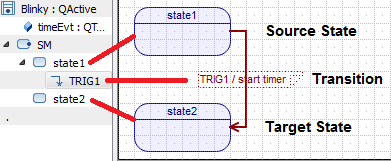
Any change in handling of events requires a change of state, that is, a state transition. Such state-to-state transitions are represented as lines that originate on an edge of the source state and terminate with an arrow () on an edge of the target state.
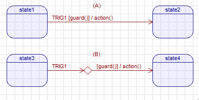
However, often you only need to simply react to an event (by executing some actions) without changing states. In UML such a situation should be modeled with internal transitions. Internal transitions are represented in UML as text inside the state compartment (see part (A) of the figure below).
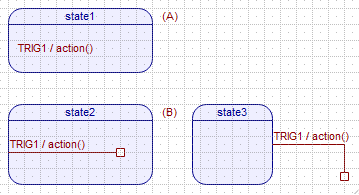
In QM™ internal transitions are represented as a transition without a target (see part (B) of the figure above). Visually, the end of such transition shows as a small rectangle () instead of an arrow ().
Make sure that the State Machine subwindow is active. In the State Machine Toolbox click on the Transition tool and release the mouse button (don't drag the tool off the toolbar). At this point, when you hover the mouse over the active state diagram, the mouse pointer changes to the transition tool with the "forbidden" icon (), because a transition can only be added to an edge of a state. When you hover the mouse over a state edge, the mouse pointer changes to the transition tool with the anchor (). To add the transition at this source state, press the mouse button and drag the transition end out. As you drag the transition, the mouse pointer changes to a hand and the transition end takes the shape of a square ().
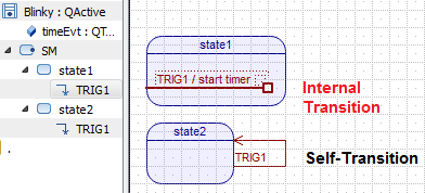
If you drop the transition end when it still shows as a square (), the transition will become an internal transition (a.k.a. state reaction). The following animation shows how to add an internal transition:
To add a regular state-to-state transition, you need to drag the transition end to an edge of the target state. As you drag the transition end over a state edge (which could be the source state), the mouse pointer changes to a hand shape with an anchor () and the transition end takes the shape of an arrow. If this is the desired target state, drop the transition end at this point. The following animation shows how to add a state-to-state transition:
Transition item can be configured by the Transition-Specific Property Sheet.
The Transition property sheet contains the following properties:
Every transition in QM™ must have an explicit trigger, which is the name of the signal of the event that triggers the transition (NOTE: QM™ does not support trigger-less "anonymous transitions"). The trigger shows up in the Text Box associated with the Transition.
The trigger property must be a legal symbolic constant representing the signal of the triggering event. Typically, the event signals are enumerated constants, and by the C convention are all in uppercase, for example: TIMEOUT, OPEN, CLOSE, etc.
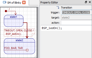
_SIG to the trigger property you type into the Property Editor. For example, triggers TIMEOUT, OPEN, and CLOSE will appear in the generated code as TIMEOUT_SIG, OPEN_SIG, and CLOSE_SIG, respectively.The trigger property might also be a list of event signals that trigger the transition, which is a shorthand notation for a group of transitions that all target the same state and execute the same actions. For example, you might provide a single trigger property as: "TIMEOUT, OPEN, CLOSE", which means that all of the listed signals will trigger the transition.
case statements that "fall through" into each other.As an extension to the UML, QM™ supports also a special type of CATCH_ALL transition trigger. This trigger means that the transition will be trigger by any event that is not handled explicitly by any other transition in the state.
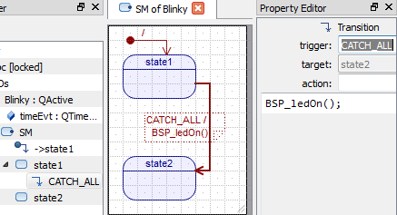
CATCH_ALL transition per state. The QM™ code generator will report an error if encounters multiple CATCH_ALL triggers in a given state.The target property is not editable directly, but rather it is determined geometrically by the end-point of the transition. For state-to-state transitions, the target property lists the target state at which the end-point () terminates. For internal transitions with the square end-point (), the target property shows internal.
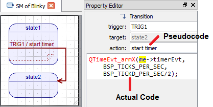
A Transition can have an optional action property, which consists of two entries: pseudocode and code (see Transition Property Sheet). Only the code part of the action property is relevant for the code generation. The pseudocode field is designed only to be displayed in the diagram to avoid clutter by minimizing the amount of text to display next to the transition shape.
Pointer to the Triggering Event (e): The transition action code often needs to access the triggering event, which is provided as the e pointer of the type (QEvt const * const). This means that you have read-only access to the event, and you cannot change the e pointer.
Accessing Event Parameters: To access event parameters of the triggering event, you typically need to downcast the event pointer e. This downcast is always based on the transition trigger (signal of the triggering event, see Transition Trigger), which means that you must always know the event type (event class) associated with the trigger.
Once the transition item is selected as the Current Item, you can see the boundary of the Text Box associated with the transition. The Text Box allows you to move and resize the transition text by dragging it around or dragging the Text Box Handle (see the screen animation below).
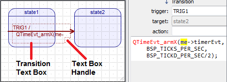
The Text Box allows you to move and resize the transition text by dragging it around or dragging the Text Box Handle (see the screen animation below).
<TRIGGER>/ string. If the pseduocode entry is not empty, regardless of the contents of the code entry, the pseudocode is displayed in the same line as the <TRIGGER>/ string. Finally, if the pseudocode is empty, but the code entry is not empty, the code is displayed in the Text Box of the transition, however, the actual code is displayed in a line below the <TRIGGER>/ string. Of course, to see the text, you need to sufficiently expand the Text Box of the transition, as shown in the animation above.To move a transition, either within the original source state or to a different source state, you need to hover the mouse over the source-end of the transition until the mouse cursor changes to "hand with an anchor" (). At this point you can start dragging the source-end to a different state edge, which could be a different state.
At any point, you can very easily change an internal transition into a regular state-to-state transition by simply dragging the square end () and "anchoring" it at an edge of a state, at which point it becomes an arrow (). This is one of the many benefits of the "non-normative" transition notation used in QM™.
QM™ allows you to route your transitions (all connectors, in fact) any way you like. You can create any number of rectilinear segments and you can move them around. The following animation shows how the segments on both ends can be used to create new edges, how to move them, and how to remove segments.
One of the primary design objectives in QM™ was to respect your design decisions as much as possible and avoid the need to "fight the tool". In this respect, nothing is more frustrating than a tool that suddenly changes the arrangement of your transitions, after you spent hours routing them exactly the way you like. QM™ will never do that. Instead, QM™ will change at most 2 first or last transition segments attached, depending if you are moving the beginning or end of the transition.
A very important feature of state transitions in UML is the support for guard conditions (often simply called "guards"). A guard condition is a Boolean expression that can be associated with a transition, which means that the transition should be taken only when the guard dynamically evaluates to TRUE. If the guard evaluates to FALSE, the transition is not taken and any action(s) associated with the transition are not executed.
In QM™ state transitions do not accept guard conditions. Instead, you can attach any number of choice segments to the end of a transition, which creates alternative transition path(s) evaluated dynamically at run-time. You can even attach choice-segments to choice-segments to build even more complex transition paths. All this provides actually a more powerful and intuitive mechanism than simple "guards" on transitions.