QM
5.2.3
Model-Based Design Tool
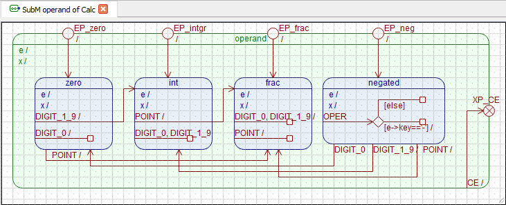
Submachine Diagram allows you to specify a composite state and all its nested substates and transitions (submachine) in such a way that it can be instantiated (and thus reused), possibly multiple times, in the context of a given state machine. You can think of submachines as "macros" or "procedures" that capture common behavior inside a given state machine in order to reuse it (as submachine states) within the context of the same state machines.
To enable reuse of a Submachine Diagram without revealing its internal structure ("black-box"), the Submachine Diagram must provide a well-defined interface on its boundary, which consists of Entry Points for attaching any incoming transitions targeting specific substates and eXit Points for attaching outgoing transitions originating in specific substates.
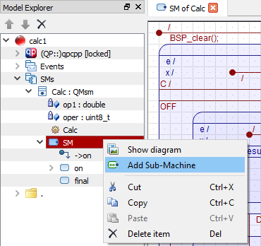
To add an new, blank Submachine Diagram in the Model Explorer, right-click on the State Machine (SM) to which you want to add the Submachine Diagram and select Add Sub-Machine from the popup menu.
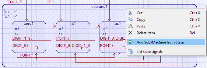
Alternatively, you can create a Submachine Diagram from an existing (composite) state. The advantage of this method is that the created Submachine will contain all the internals of the chosen composite state, including the entry actions, exit action, initial transition, as well as all the nested substates and transitions.
To create a new Submachine Diagram from a given state right-click on this state in the diagram (or in the Model Explorer) and select Add Sub-Machine from State from the popup menu.
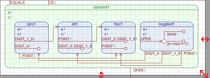
As do all diagrams in QM, the Submachine Diagram has a Drawing Canvas, which can be resized by dragging the outside edges or the bottom-right corner of the diagram. However, the special feature of Submachine Diagram is that resizing the canvas always simultaneously resizes the outline of the composite state (shown in green).
To delete a Submachine Diagram, you need to select it as the Current Item, either by clicking on the (green) state outline or in the Model Explorer. After this, you can delete the Submachine in several ways: (1) click the button in the Explorer Toolbar; (2) press the keyboard shortcut; or (3) right-click on the state diagram and choose the option from the pop-up menu (see the screen animation below).
The Submachine Diagram item can be configured by the State-Specific Property Sheet.
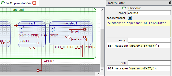
The state-item property sheet contains the following properties:
The submachine name should be a valid function name in C or C++. Typically, you should strive for a short and punchy name that captures the nature of the submachine. For example, a submachine in which a system remains "on" could be named on. To keep with the naming conventions used in QM examples, it is recommended to use lower-case names of submachines.
The documentation entry in the Submachine Property Sheet allows you to provide documentation to the submachine. The QM code generator parses the documentation text and can generate comments from it in the auto-generated code.
A submachine can have an optional entry action. You provide this action in the Submachine Property Sheet (see also the screen shot above). If defined, the entry action shows up in the upper-left corner of the submachine outline. The Submachine entry action behaves in exactly the same way as the entry action to a state.
A submachine can have optional exit action. You provide this action in the Submachine Property Sheet (see also the screen shot above). If defined, the exit action shows up in the upper-left corner of the submachine outline (below the entry action, if present). The Submachine exit action behaves in exactly the same way as the exit action to a state.